FITTING AN OEM WIDESCREEN SATELLITE NAVIGATION SYSTEM
IN A NON-NAV LEXUS GS
Click each photo to view a bigger version.
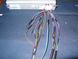
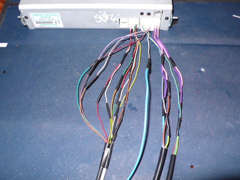
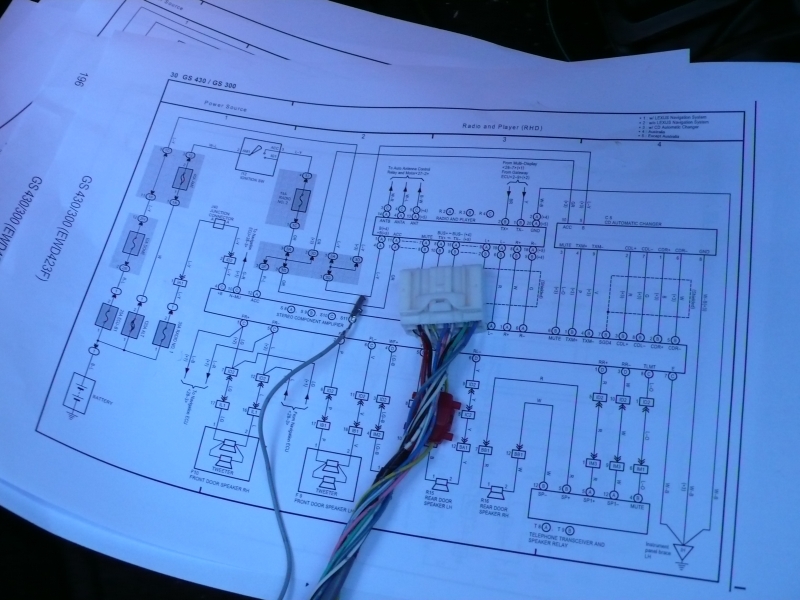
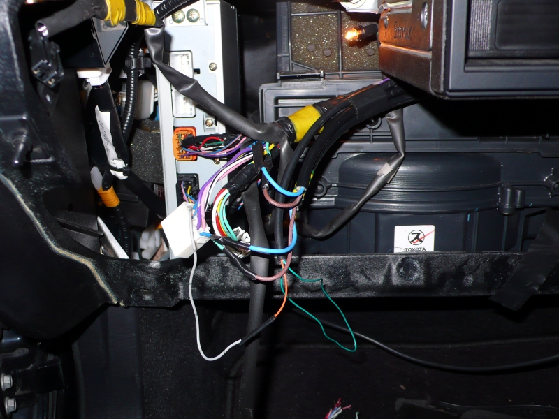
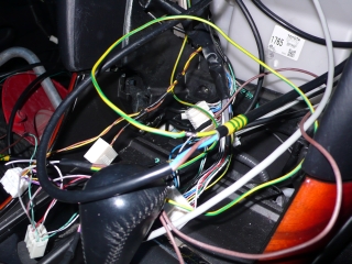
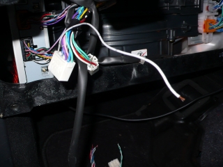
Navigation unit end of wiring harness. Some colours on these
plugs don't match the ones in the Lexus wiring diagrams, but this
doesn't matter as long as the correct pins are used! You can't
see in this
picture, but one of the three-core cables has been marked with tape at
each end so that they can be told apart. All connections have
been soldered and taped, with each pair of wires cut at a different
position so that the joints are staggered instead of being in one fat
bundle. In addition, staggering the joints reduces the risk of a
short-circuit if any of the tape slips off.

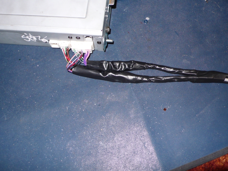
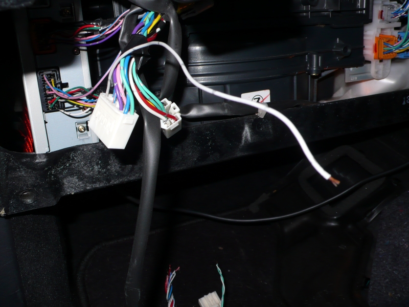
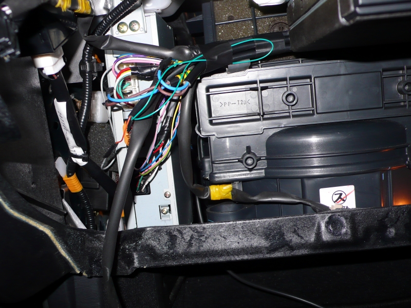
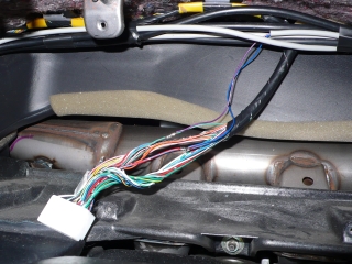
The same connections sleeved and taped. Because of the staggered
joints there's no big bulge in the harness and the sleeves fit over
nicely.
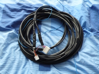
This is as much as can be done without installing the cables in the
car, as you don't want to try routing the plugs themselves through the
car's cable channels!

A pair of DPDT relays have been fitted here, end-to-end. This
is not required when fitting the navigation system, I've added these to
be able to replace the navigation unit's RGB+Sync signal with my own,
part of another project.
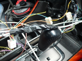
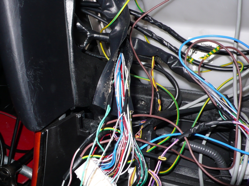
The same pair of relays taped up. Note that two grey cables
exit to the right. One of these is the cable
entering from the boot, the other contains the three wires that go to
the combination meter and diagnostic port. The original wires
have
been pulled out and the three wires threaded through instead.
This
gives the wires greater protection. The two grey cables to the
left come from the relays, one goes to a SCART plug and the other
carries the power feed for the relay coils.
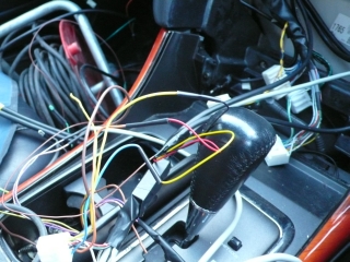
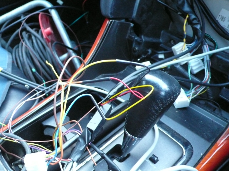
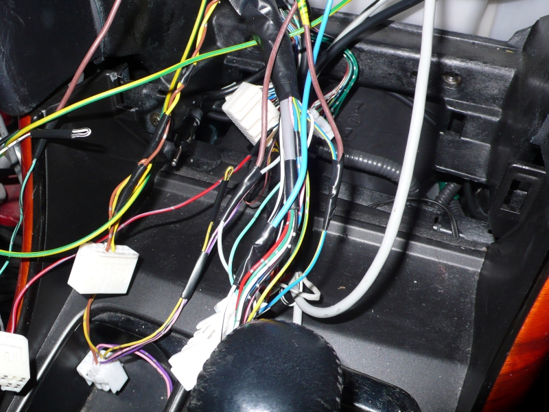
The connections are starting to take shape now. The black
cable that leads out towards the top of the picture is another example
where the original wires have been pulled out and the sleeve re-used
for protection. This one contains the REV and SMUT wires from
the navigation unit in the boot.
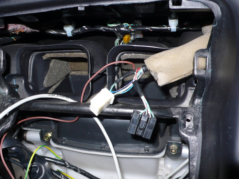
The three-core mains cables make a stop-off here on their way to the
amp, so that power can be fed to the navigation unit in the boot.
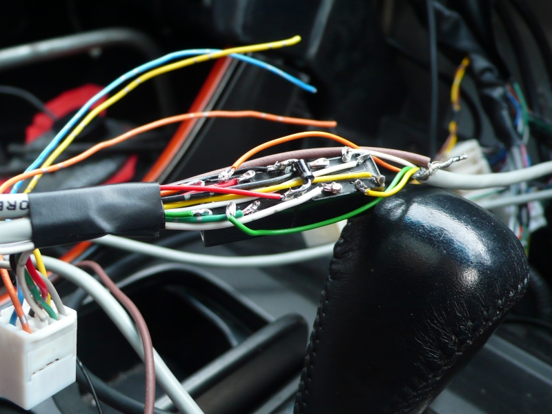
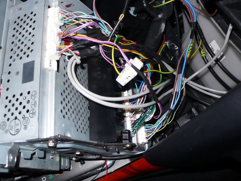
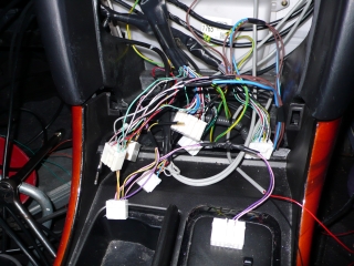
These are the plugs that go into the back of the combination meter,
otherwise known as the instrument panel! The violet and blue
wires head just out of shot to the right, then double-back towards the
radio. As you can see in this picture, all of the connections
are being soldered.

The white plug on the left plugs into the clock. The brown
wire is tapped into the wire that's used to dim the clock when it's
dark, and does the same job for the touch-screen display.

I had a spare R3 plug, so instead of cutting this one off I just tapped
into the wires feeding it. Also visible in this picture is the
PKB (parking brake) wire, I've taped it up instead of connecting it,
but will be connecting it soon as it's required to access the diagnostics screen.

These two wires are easy to miss, as they don't appear in the radio or
navigation wiring diagrams! Leave them out and the buttons on
the display won't illuminate. Connect them and the buttons
can be dimmed along with the rest of the dashboard lights. Nice!
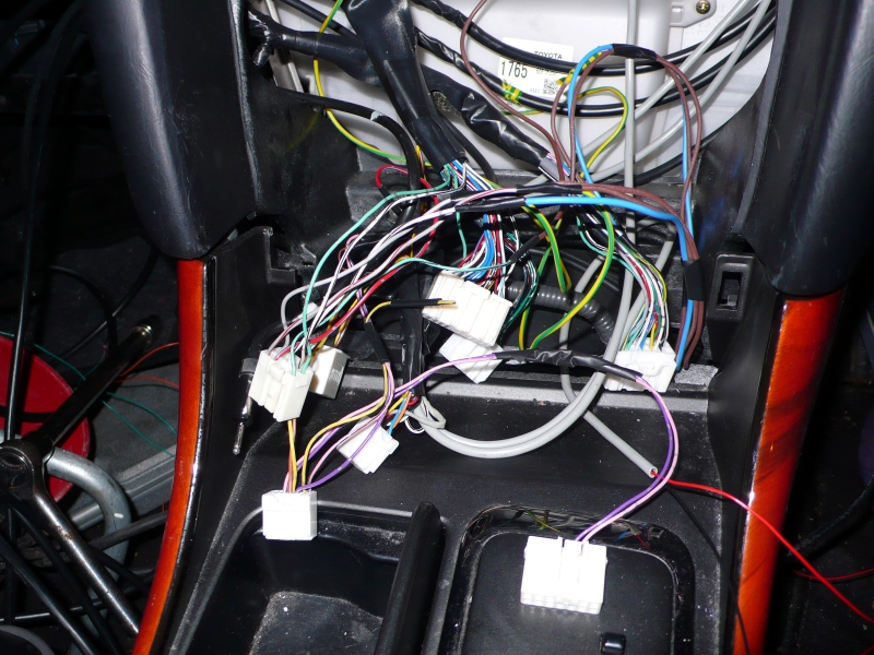
Here's the spare R3 plug, connected to M3.

All plugged in!
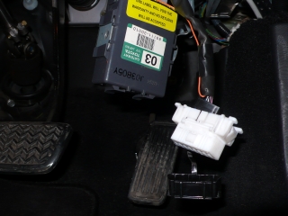
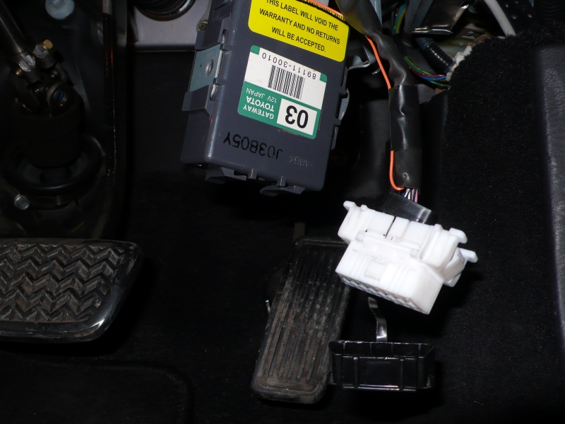
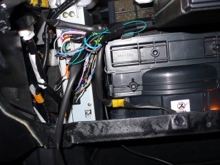
Don't forget the gateway ECU! Fortunately the plug for this is
already there, it's just a case of plugging the box in. It
should come with a bracket, but if it's from a LHD car it won't bolt in
place. Fortunately it'll fit roughly where it belongs (up
above the accelerator, next to some other modules) without rattling
around, if you unclip the relay that's already up there and clip it onto the slot on the
gateway ECU's bracket.
Also
in this picture you can see the orange wire that connects to the
diagnostic plug. This was fed through the same grey sleeving
that went to the combination meter, then dropped down.

The N-MU (navigation mute) pin is missing from the S10 plug in non-nav
cars, or at least it was on mine! Fortunately I had a spare
R2 plug which had three spare pins that fit S10, so I scrounged one...
...and popped it in! If you need to do this you'll need a
small jewellers' flat-blade screwdriver to release the plastic bar in
both plugs and pop out the pin.

The wires to the front-right speaker are cut and the two three-core
cables connected to the ends. Get the cables the right way
round or the navigation unit will be talking to the amp instead of the
speaker! The green/yellow cores were cut off behind the
radio, and the same is done here. Also visible in this
picture is the REV wire. I've not bothered connecting it, so
I've looped it back and stuffed it into the sleeving out of the way.
The orange SMUT wire has been connected to the newly-fitted N-MU
pin.
All taped up and plugged back in.
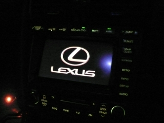
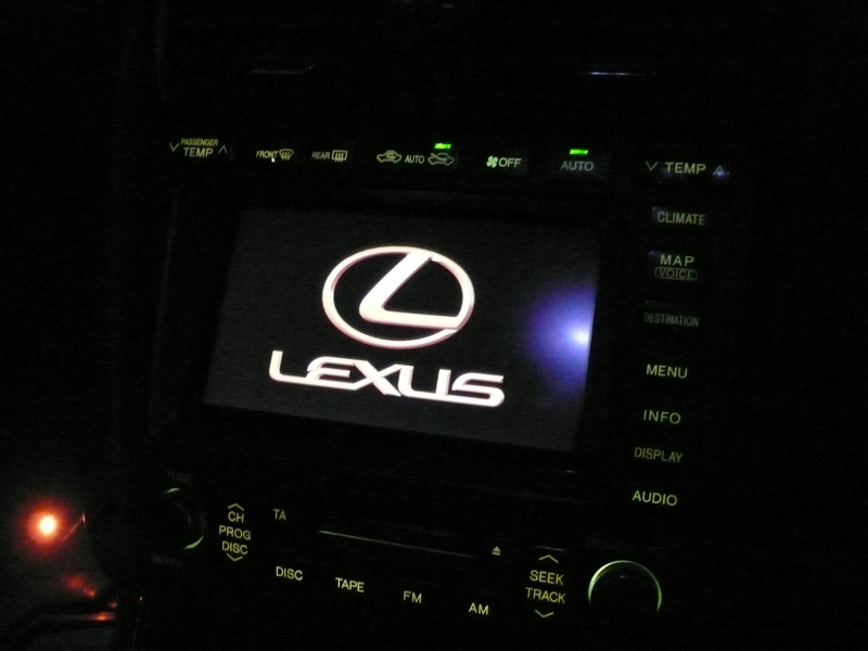
It boots!
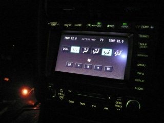
It controls the aircon!

It plays music!
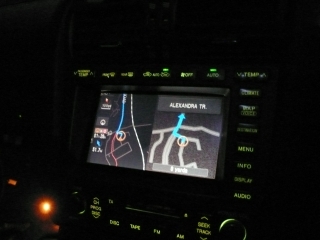
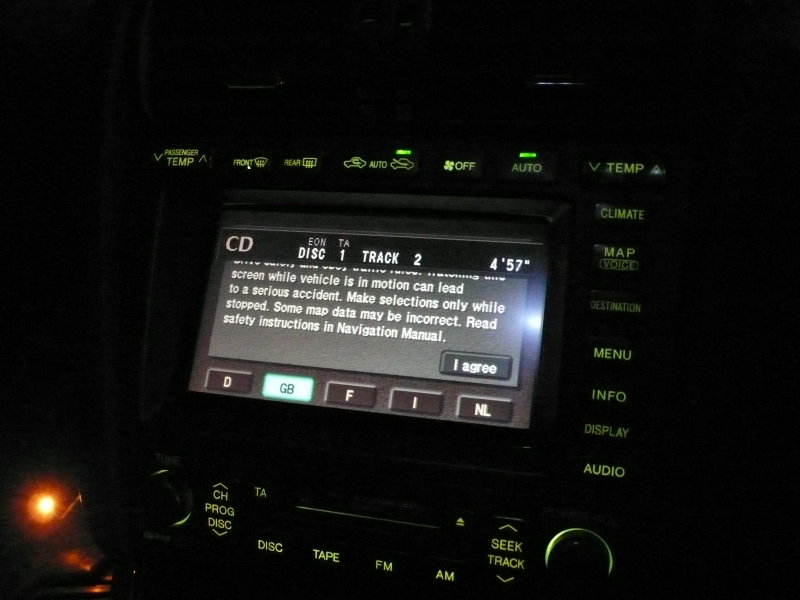
Oh, and it navigates! The project has reached its destination!